
Korg SQ-1 mod - Start/Stop control
It can be done:
I was researching how to mod the SQ-1 to respond to Start-Stop transport signals. There is a simple method with one NPN transistor and a 100k resistor which can be found in this Reddit post.
Here is how the transistor-resistor circuit ended up looking:


However, this mod is only reacting to the voltage high transition when pressing Start but won't react to voltage low transition when pressing the Stop button. On top of that the transport control signal from an external device is not 5V for Start to 0V for Stop. Instead it is 5V for Start and no voltage for Stop. It functions like a on off switch where the circuit breaks rather than a change of voltage to ground level. That means that the components in the circuit such as capacitors do not discharge but remain suspended in the state they were when the circuit was turned off.
So this simple mod will only send signal whenever 5V is received: once for SQ-1 Start and once for SQ-1 Stop. So you have to press the Start button on your external device a second time to change the SQ-1 state once.
So I looked into how to detect the raising edge and the falling edge of the signal and for this the Gate to Trigger circuitry is the solution. One capacitor and one resistor are what is necessary to get the raising edge 5V signal (Start) to convert to a trigger.
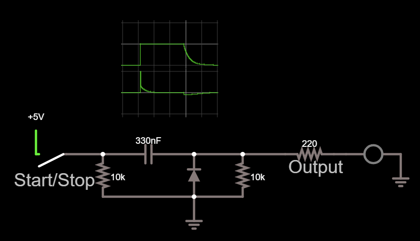
The negative edge is filtered out and considering that the transport control voltage is a no voltage signal rather than 0V there is no signal to create a trigger for when the falling edge.
But there is a solution: invert the signal. Meaning to create an inverted gate to the trigger circuit. For that we need an NPN transistor so it sees voltage when the voltage is off (stop). When the transistor detects no voltage at the base it lets the voltage from the collector pass through. It functions exactly like the other Gate to Trigger circuit but flips the polarity of the input signal so now we have a trigger signal on the no voltage (Stop) input signal.

But this is not good enough because the short trigger signals are too short for the SQ-1 to respond to. So we need something to hold the trigger for a while, like 50ms or so, enough for the SQ-1 circuitry to detect and respond to the 5V signal. The best component for doing that is the NE555 timer in monostable mode. Input is on pin 2 and output is on pin 3. But what we're interested in is the resistor at pin 7 to 5V R1 and the cap at pin 6 to ground C1 to (right side of the image). The values of these two controls how long the timer holds the voltage.

This is the default circuit so it needs to be adapted a bit. For what I needed a 100k resistor for R1 and 330nF cap at C1 to ground were the best case scenario because those were the values I had available. But you can use different values as long as they provide you with long enough triggers for SQ-1 to react to.

I wouldn't go lower than 50ms as the SQ-1 circuitry becomes unreliable in detecting your input control signal. The only thing I would have in mind is that if you lower the R1 value below 100k there is going to be more current drawn from the power source.
When adding the inverted gate to the trigger circuit the two circuits need to be separated so they don't interfere by adding diodes on the input and on the output.
When put together the circuit should look something like thins:

This circuit draws power from the USB connector on the PCB inside the case (see the pic at the bottom of this page). You need a wire for the 5V to pin 8 on NE555 and the ground to pin1. The output connects to the 100k resistor on the simple transistor-resistor circuit provided at the beginning of this blog and the out is connected to the tip connector of the audio jack. If you want to use the battery case you could connect the power to the 3V battery wires and it should work. I did test the breadboard with two AAA batteries and the NE555 does drive the SQ-1 stop/start.
When it came time to assemble the components I did consider that if I used circuit board it might be too bulky to fit inside the case so I went this route:
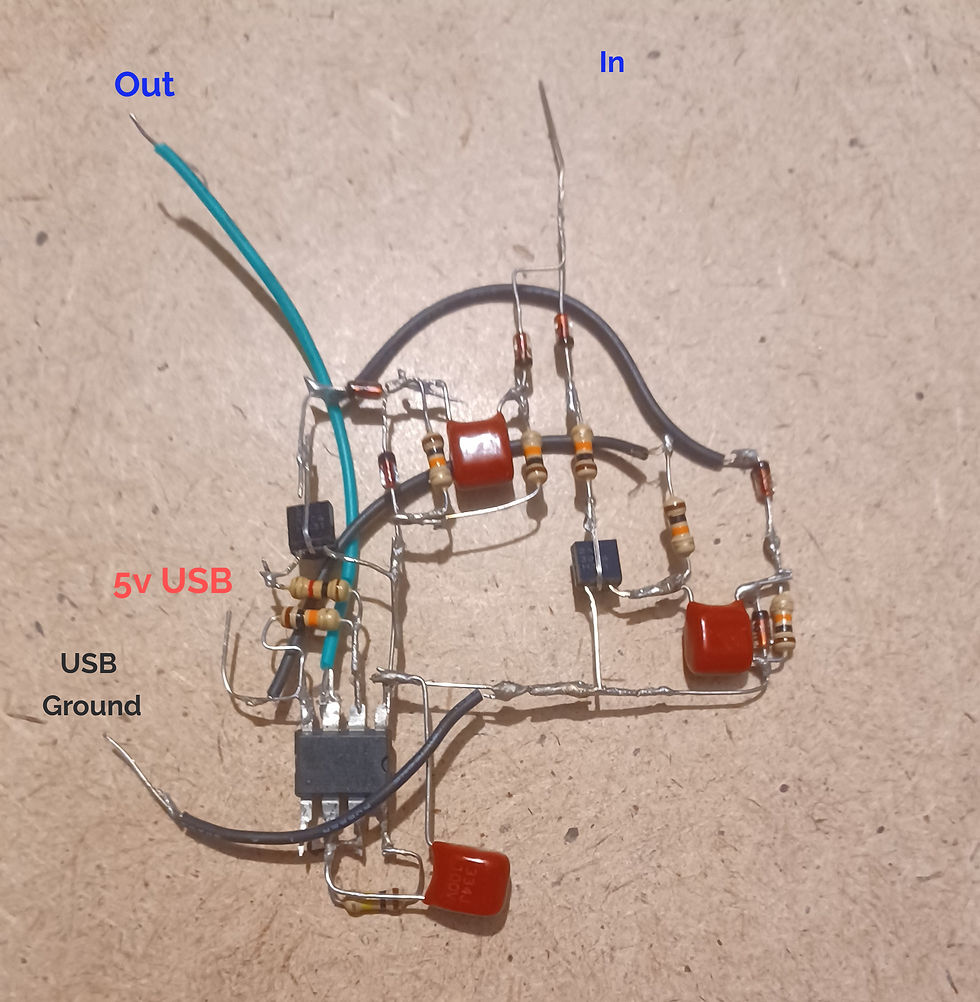
And to avoid possible shorts inside the case I wrapped it up in Scotch tape like this:

Everything is minimally invasive. Two connections for the front board to control the Start/Stop button, and two connections for the USB to power the NE555. I used replaced the battery door with another plate which I drilled a hole for the connector. However, the audio jack takes room from the battery case so I won't be able to fit batteries inside. I'm keeping the SQ-1 wired anyway.

Here is a SQ-1 teardown video.
PCB USB connections:

Comments